+86-13516964051


Choosing the right Pressure Die Casting Die is not a simple purchase decision. It is a production engineering decision involving alloy behavior, machine capacity, part geometry, and expected tool life. A die that performs well for a small zinc housing may fail quickly when used for a large aluminum structural component.
Industry reports show why this decision matters. Grand View Research identifies lightweight vehicle production as a major driver of die casting demand. The U.S. Department of Energy also links aluminum casting with vehicle weight reduction and improved energy efficiency. Meanwhile, the North American Die Casting Association highlights thermal control, die materials, lubrication, and process monitoring as key influences on casting quality. These findings point to one practical truth: the cheapest die is rarely the lowest-cost solution.
A reliable selection process should examine projected shot volume, casting wall thickness, filling speed, cooling-channel layout, and maintenance access. For example, a poorly balanced cooling system can leave hot spots near a thick boss. That small defect may later become porosity, soldering, or premature die cracking. Material choice also requires care. Premium tool steel helps, but it cannot correct an unsuitable design.
Real production experience often exposes uncomfortable assumptions. A die may meet the drawing but still create excessive trimming, flash, or cycle-time losses. Therefore, this guide evaluates the Pressure Die Casting Die through measurable criteria, supplier capability, simulation evidence, and planned maintenance. Specifications matter. So does honest review.
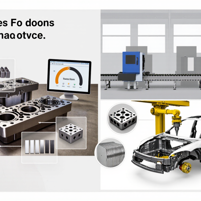
Defining part requirements is the practical starting point for selecting a pressure die casting die. Record the alloy, part weight, wall thickness, dimensions, tolerances, surface finish, and expected production volume. Small details matter. A thin rib may need stronger filling control, while a deep pocket can increase ejection and cooling difficulty. Specify draft angles, slides, cores, and any undercuts before requesting a die design.
The casting machine must also match the die and part. Check clamping force, shot weight, injection speed, metal pressure, and available die space. The alloy’s pouring temperature affects thermal fatigue and die life. Cooling channels should follow hot areas, not simply repeat a standard layout. Venting deserves equal attention because trapped air can cause porosity, blisters, or incomplete filling. Do not guess. Use filling analysis where possible, then confirm the findings through controlled trials.
In production reviews, a common mistake is treating the part drawing as complete information. It rarely is. Ask about cycle time, trimming method, inspection equipment, lubrication, and acceptable repair limits. A polished surface may require different steel preparation than a hidden structural face. The first estimate is often wrong, especially when tolerances are tightened without checking machining or shrinkage. Leave room for maintenance, safe die handling, and insert replacement. That decision may seem minor during design, but it can determine whether the die remains stable after repeated thermal cycles.
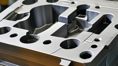
Choosing a pressure die casting die begins with the production alloy, part geometry, and expected cycle count. Aluminum alloys often require hot-work tool steel with strong thermal fatigue resistance. Zinc alloys may permit different steel grades and less severe thermal loading. The die must withstand repeated heating, cooling, injection pressure, and abrasive metal flow.
Design features matter as much as material selection. Use generous fillets to reduce stress concentration around corners. Add suitable draft angles for clean ejection and fewer surface scratches. Cooling channels should maintain even temperatures, especially near thick sections and sharp transitions. Proper vents and overflow wells help release trapped air and reduce porosity. Replaceable inserts can lower repair time, but poorly positioned inserts may create leakage or alignment problems. Small details become expensive later.
Tips: Match the steel hardness to the casting alloy and production volume. Check cooling balance with thermal simulation or trial measurements. Keep vent paths short and clean. Review gate location with the filling pattern, not guesswork. A common mistake is choosing the hardest material without considering toughness. No die is perfect. Early testing may reveal uneven wear, blocked vents, or excessive heat near the gate. Record those findings and adjust the design before full production.
| Selection Dimension | Recommended Material or Feature | Typical Specification or Design Guideline | Best Suited For | Main Benefit | Important Limitation |
|---|---|---|---|---|---|
| General die body material | H13 hot-work tool steel | Usually heat-treated to approximately 44–52 HRC; verify toughness and cleanliness requirements with the steel supplier. | Aluminum, magnesium, and zinc die casting dies requiring balanced performance | Good combination of thermal-fatigue resistance, toughness, and machinability | Requires controlled heat treatment and stress relieving to reduce cracking and distortion |
| High thermal-fatigue exposure | H11 hot-work tool steel | Commonly used around 42–50 HRC when higher toughness and reduced thermal-shock sensitivity are priorities. | Large or heavily cycled dies with repeated heating and cooling | Strong toughness and reliable resistance to heat checking | May provide lower wear resistance than a harder die grade in abrasive conditions |
| High-wear areas and repairable inserts | Premium hot-work steel or replaceable hardened insert | Use selectively in gates, slides, cores, and sharp-detail regions; maintain a compatible hardness and thermal-expansion behavior. | Long production runs, abrasive alloys, and localized wear zones | Extends die service life and reduces the cost of replacing the complete die half | Poor insert fit or insufficient support can cause cracking, flash, or premature loosening |
| Thermal conductivity at localized hot spots | Copper-alloy cooling insert | Use only in selected areas where heat removal is difficult; isolate and support the insert against casting pressure and erosion. | Deep cores, thick sections, and areas near intensive thermal loads | Improves heat transfer and can reduce localized soldering or cycle-time limitations | Lower hardness and possible chemical compatibility concerns require careful placement and maintenance |
| Surface protection | Nitriding or suitable PVD coating | Apply after final heat treatment and finishing; control case depth or coating thickness to avoid dimensional interference. | Gates, slides, cores, and surfaces exposed to erosion or soldering | Improves surface hardness, release behavior, and resistance to wear or sticking | The treatment cannot compensate for poor cooling, incorrect lubrication, or inadequate die design |
| Casting alloy compatibility | Match die grade and protection to the alloy | Aluminum and magnesium generally demand stronger thermal-fatigue control; zinc usually places greater emphasis on wear, precision, and long cycle life. | All production programs | Reduces premature heat checking, erosion, soldering, and dimensional instability | A material suitable for one alloy and cycle profile may not be optimal for another |
| Cooling system | Balanced conformal or drilled cooling channels | Keep channels sufficiently separated from the cavity and from each other; avoid sharp bends, stagnant zones, and excessive proximity to thin die sections. | High-volume production and parts with uneven wall thickness | Improves cycle consistency, reduces thermal gradients, and supports dimensional control | Complex channels increase manufacturing cost and require leak testing and regular cleaning |
| Gate design | Short, balanced gate with controlled metal velocity | Position the gate to fill thin sections first where possible and avoid direct impingement on cores or opposing walls. | Parts requiring good surface quality, stable filling, and low porosity | Reduces turbulence, erosion, cold shuts, and inconsistent filling | Gate location may increase trimming requirements or restrict part layout options |
| Venting and vacuum assistance | Distributed vents, overflows, and optional vacuum connection | Place vents at final-fill locations and use overflows to capture cold metal, oxides, and trapped gas. | Thin-wall parts, pressure-tight components, and complex filling patterns | Improves air evacuation and reduces gas porosity and incomplete filling | Vents and overflows require trimming, cleaning, and protection from blockage |
| Draft angle | Use the minimum angle that supports reliable ejection | A common starting range is about 0.5–2° per side, with more draft often needed for deep walls, textured surfaces, or difficult release conditions. | Most die-cast components | Reduces drag marks, scuffing, sticking, and ejection force | Excessive draft can affect assembly fits, wall thickness, and functional dimensions |
| Corners and transitions | Generous radii and smooth section changes | Avoid sharp internal corners; use radii that suit the required wall thickness, filling pattern, machining allowance, and die strength. | Complex housings, structural parts, and high-integrity castings | Improves metal flow and reduces stress concentration, cracking, and die heat checking | Larger radii may require changes to the product geometry or downstream machining |
| Ejection system | Evenly distributed ejector pins with adequate support | Locate pins on strong, non-cosmetic areas and balance the ejection force to prevent distortion or sticking. | Parts with deep pockets, ribs, cores, or large projected areas | Improves release reliability and reduces deformation and pin marks | Poor placement can create visible marks, local stress, or casting distortion |
| Die size and support | Rigid die structure with sufficient backing and alignment | Design for clamping force, injection pressure, projected area, thermal expansion, and safe access for maintenance. | High-pressure production and large projected-area castings | Limits parting-line flash and maintains dimensional repeatability | A heavier structure increases material, machining, handling, and storage costs |
| Maintenance strategy | Modular wear components and accessible service points | Include replaceable inserts, removable slides, cleanable vents, drain points, inspection surfaces, and clear identification of critical dimensions. | Long-running programs and dies subject to frequent cleaning or repair | Shortens downtime and makes wear monitoring more predictable | More components require accurate assembly, spare-part control, and documented maintenance procedures |
Choosing a pressure die casting die starts with the machine, not the drawing. A die may fit the product but fail under real production pressure. In my experience, engineers should check clamping force, tie-bar spacing, shot sleeve size, and maximum die dimensions together.
Begin with the projected casting area and injection pressure. These values help determine the required clamping force. The die must also match the machine’s opening stroke and ejection system. Check the die thickness carefully. A small mismatch can prevent proper mold closure. Do not overlook the shot sleeve and plunger relationship.
Before production, review filling and solidification data. Run a controlled trial and inspect flash, porosity, cycle time, and die temperature. Measurements are more reliable than assumptions. A calculation can still be wrong. Leave room for adjustment around vents, cooling flow, and ejector timing. That practical flexibility often protects the die during long production runs.
How to Choose the Right Pressure Die Casting Die?
Cooling design strongly influences cycle time, surface quality, and die life. Place cooling channels near thick sections, but maintain enough steel for strength. During trials, measure water temperature at both inlet and outlet. A large temperature difference may reveal poor flow distribution. Thermal simulation helps, but physical measurements remain essential. Keep it practical.
Venting needs careful attention around ribs, deep pockets, and final-fill areas. Trapped air can cause blisters, cold shuts, or incomplete filling. Use overflow features and vent paths that technicians can clean easily. Vent depth must match the alloy and process conditions. Small gaps matter. Do not guess; confirm results through short production runs and sectioned samples.
The ejection system should release the casting without bending thin walls or damaging cosmetic surfaces. Distribute ejector pins around balanced load areas, then check marks after repeated cycles. Maintenance planning should include vent cleaning, cooling-channel flushing, lubricant control, and scheduled dimensional inspection. Keep clear records of cracks, soldering, leakage, and pin wear. In practice, maintenance intervals often need adjustment after real production begins. I have seen well-designed dies lose stability because cleaning was treated as an occasional task. A simple checklist is useful, though it cannot replace experienced inspection.
Cooling, venting, ejection, and maintenance systems should be evaluated together because each one directly affects casting quality, cycle stability, die life, and downtime.
The percentages are practical engineering planning weights for an initial die review, not a universal industry standard. Cooling normally receives the highest attention because uneven thermal control can accelerate soldering, thermal fatigue, distortion, and premature die failure.
Selecting a pressure die casting die requires more than comparing an initial quotation. Die life, part quality, lead time, and total cost are closely connected. In production reviews, I examine expected shot count, alloy temperature, clamping pressure, and cooling design. A die rated for 100,000 shots may perform differently under abrasive alloys or frequent thermal cycling. Numbers need context.
Quality appears in stable dimensions, clean surfaces, and predictable flash control. Ask for documented tolerances, inspection methods, and sample-part results. A polished cavity cannot compensate for weak venting or uneven cooling. Small defects become expensive after machining and assembly. Still, perfection on the first trial is uncommon. Plan room for tuning.
Lead time should include design review, steel preparation, machining, heat treatment, trial shots, and corrections. A fast delivery promise may hide a rushed validation stage. Confirm milestone dates and who approves changes.
Total cost includes maintenance, spare inserts, downtime, scrap, energy, and replacement tooling. A cheaper die can lose its advantage after repeated repairs. I would compare cost per acceptable part, not purchase price alone.
This measure is more honest, although it depends on realistic production data. Recheck the calculation after the first production run. Real conditions often expose assumptions that looked reasonable on paper.